Carbon Composite Disc Springs
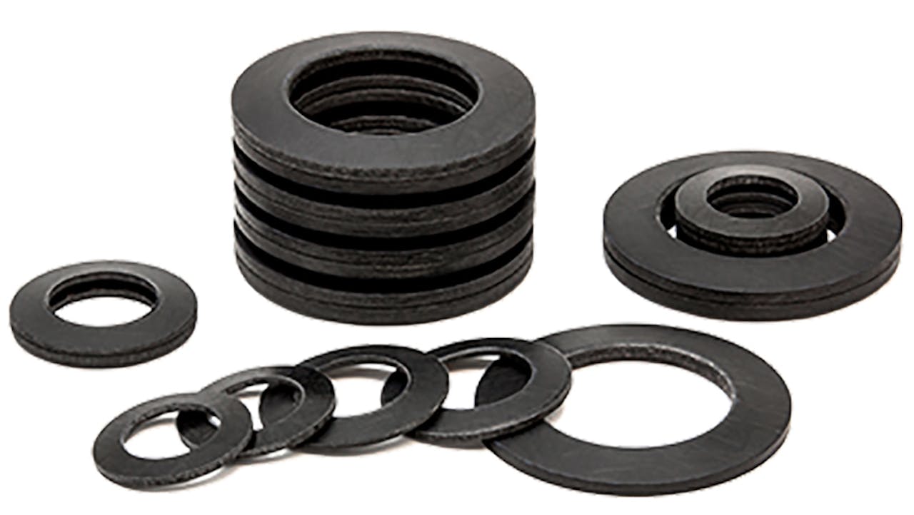
The carbon composite disc spring or carbon composite bellows spring is produced by stacking pairs of Belleville springs made of carbon fiber. In many cases, this spring is preferred over traditional coil springs or metal Belleville springs due to the additional characteristics that its composition provides. Using Carbon Fiber Reinforced Polymer (CFRP) to produce disc springs and other spring variants offers multiple performances attributes that are not possible with metal alternatives. Some of these attributes include lightweight, high-performance, no side load, tunable hysteresis, and the ability to self-align.
Carbon Composite Disc Springs Overview
Characteristics
Carbon composite disc springs are a great alternative to traditional compression springs due to the performance that they can provide while offering a lighter-weight alternative. Carbon composite disc springs are ideal for the following uses:
- Lightweight total assembly
- Fast dynamic response
- Rate and/or deflection tuning
- Thermal insulation needs
- Avoiding side loading on the interfacing hardware
- Non-magnetic spring requirements
Manufacturing
There are two common types of carbon fiber reinforced polymer springs that can replace conventional disc springs and coil springs within your applications. Details surrounding each version's capabilities and the features and benefits of the general product category are listed below for your reference. Due to our customization capabilities, we can work with multiple variations of both of these common styles.
CUSTOM MANUFACTURING
Custom Carbon Composite Disc Springs
Our composite springs are all custom made to your specifications. Our engineers will work with your design team to develop the best solution using our latest design approaches and materials.
We offer unlimited customization options from variations in size, depth, shape, and more. Unique problems require unique solutions. Let us help you develop a solution that takes your product to the next level.
Send us your specs or configure a spring.

Types of Carbon Composite Disc Springs
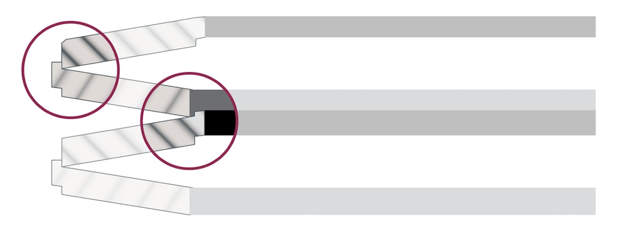
Type 1
When considering Type 1, the use of a single element on its own is not possible because the lip & flange extend past the surface of the element on one side and cannot be load bearing. A set of two elements, stacked in series, is the minimum requirement. Friction level can be manipulated to meet application specs.
| Type 1 Specs |
|---|
| Interlocking lip/flange allows a stack to be self-supporting even when only restrained at the ends |
| Typically larger than 1.38″ ID |
| Configurable for linear or non-linear load curves |
| Series / parallel |
| ~1% – 20% hysteresis |
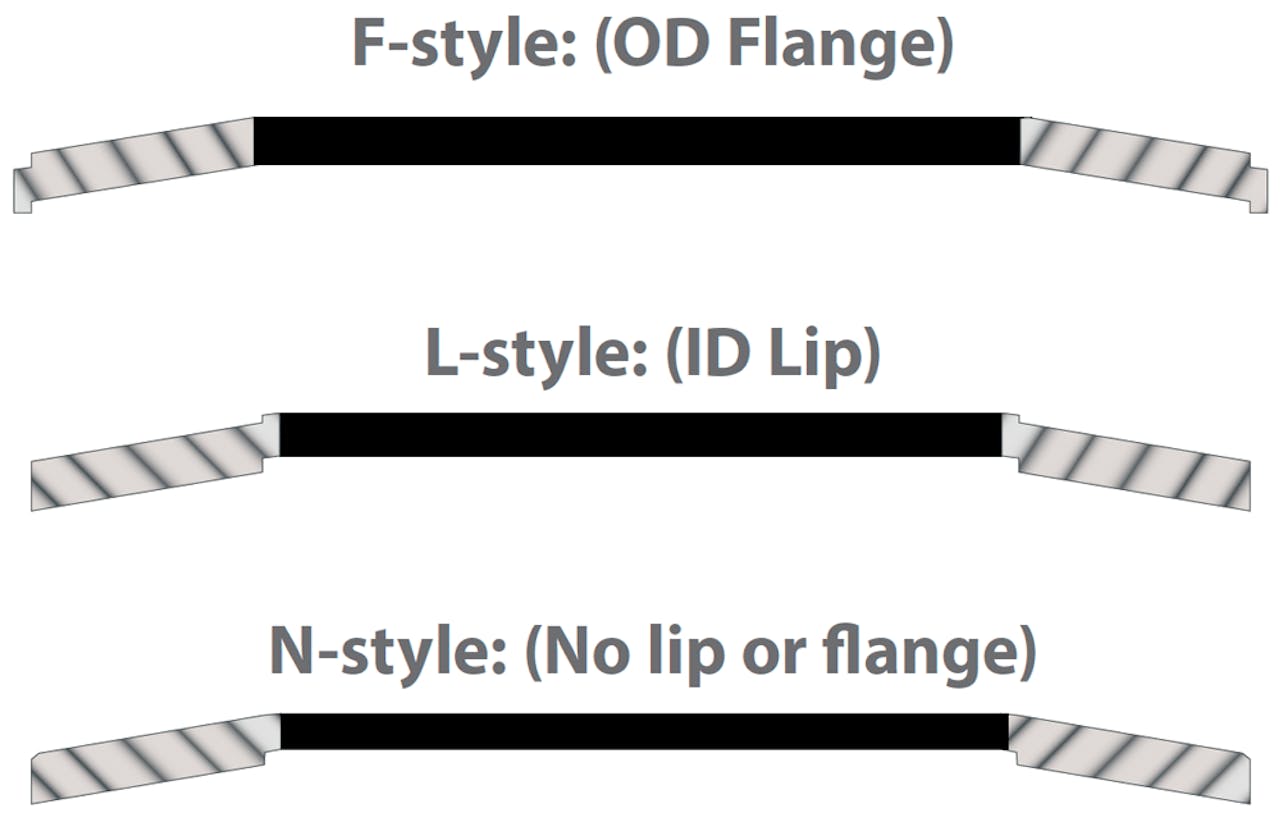
Type 2
Both type 1 and type 2 carbon fiber reinforced polymer springs that can replace conventional disc spring applications as well as installations where coil springs had been the default choice. Type 2 leverages an ID guide rod to align the elements. This function can also be performed by a guide on the OD of the elements.
| Type 2 Specs |
|---|
| ID down to .75″ are generally possible |
| Requires a full length ID or OD guide to align a stack |
| Can be used as single elements or stacked in series / parallel |
| One part style for a given base rate |
Features & Benefits
Lightweight
Carbon composite disc springs can achieve up to 60% weight savings depending on application.

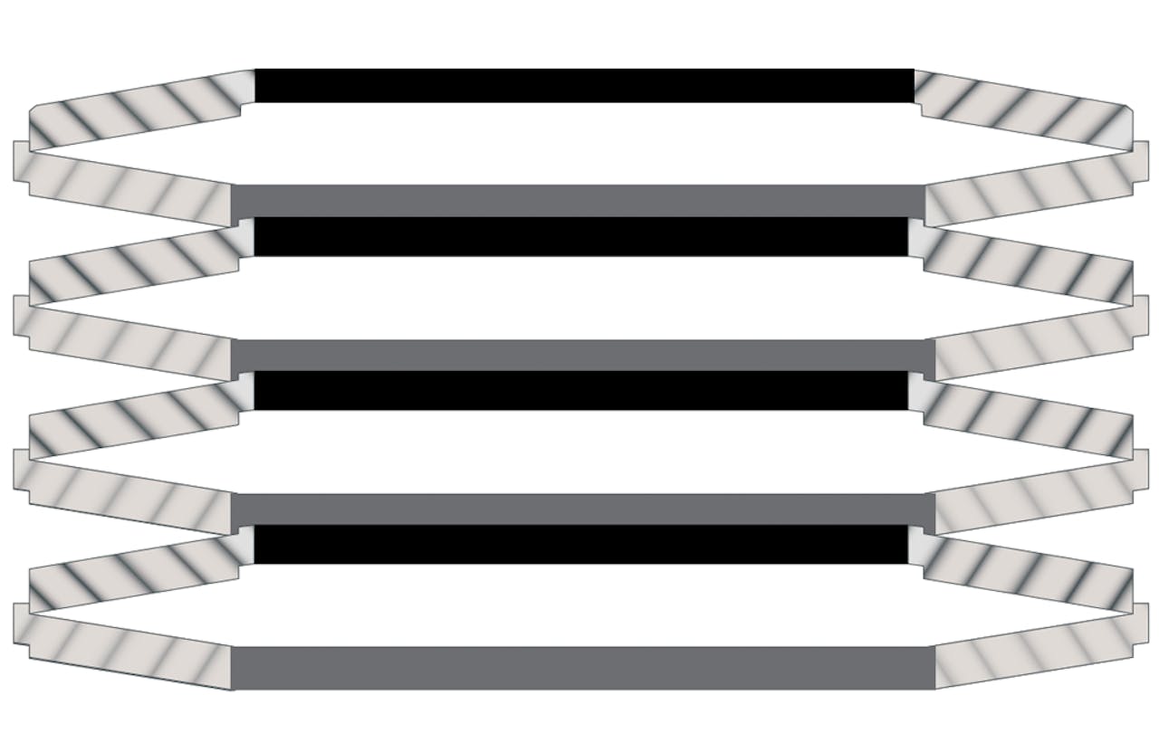
Ways to Manipulate the Stack
Manipulate your spring by changing how the elements are oriented. This gives you flexibility on the final spring specs without the need to manufacture new springs. To the right you can see a mixed stack of series and parallel orientation. Below and to the left is an example of series stacking. Below and to the right is an example of parallel stacking.
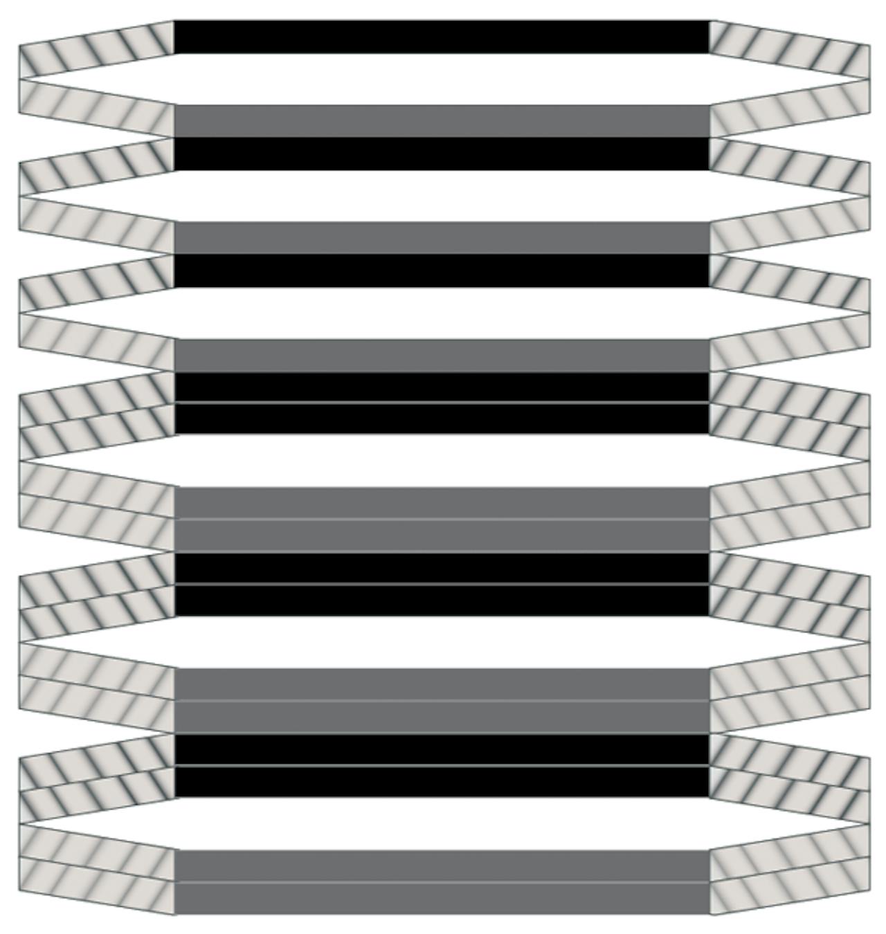
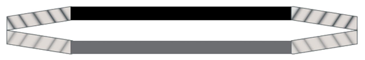
Add a Series Set of Elements
- Stack Rate: Decreases
- Stack Deflection: Increases
- Stack Height: Increases
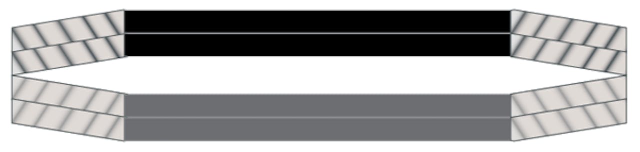
Make a Series Set into a Parallel Set
- Stack Rate: Increases
- Stack Deflection: Remains unchanged
- Stack Height: Increases
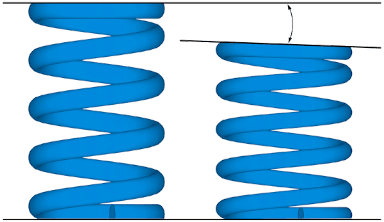
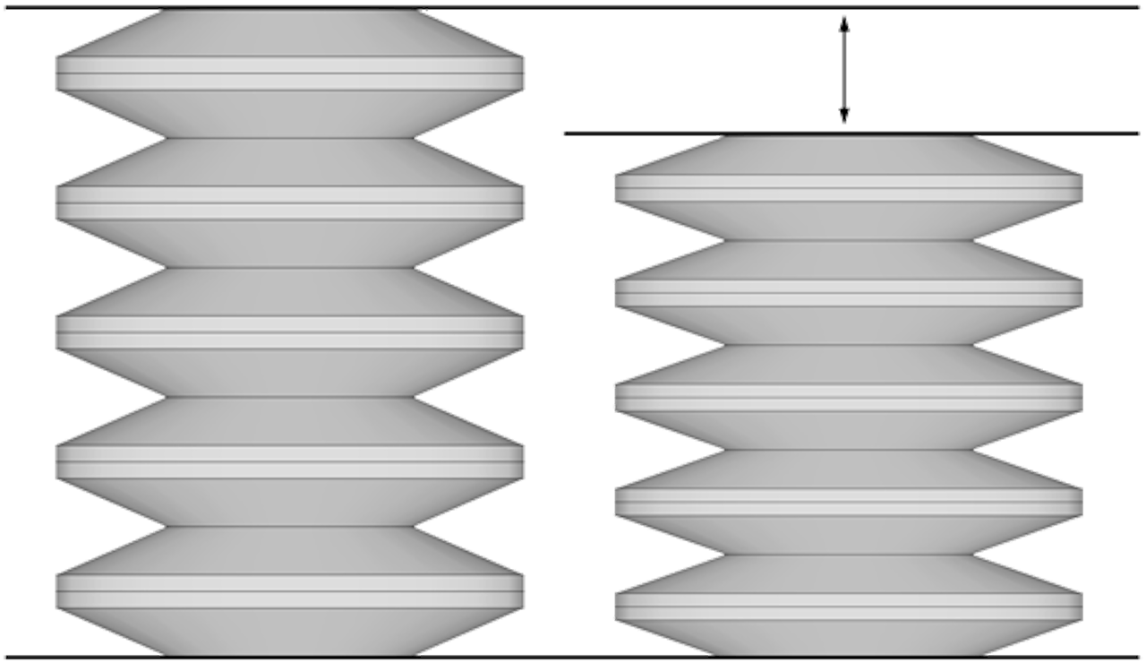
No Side Load
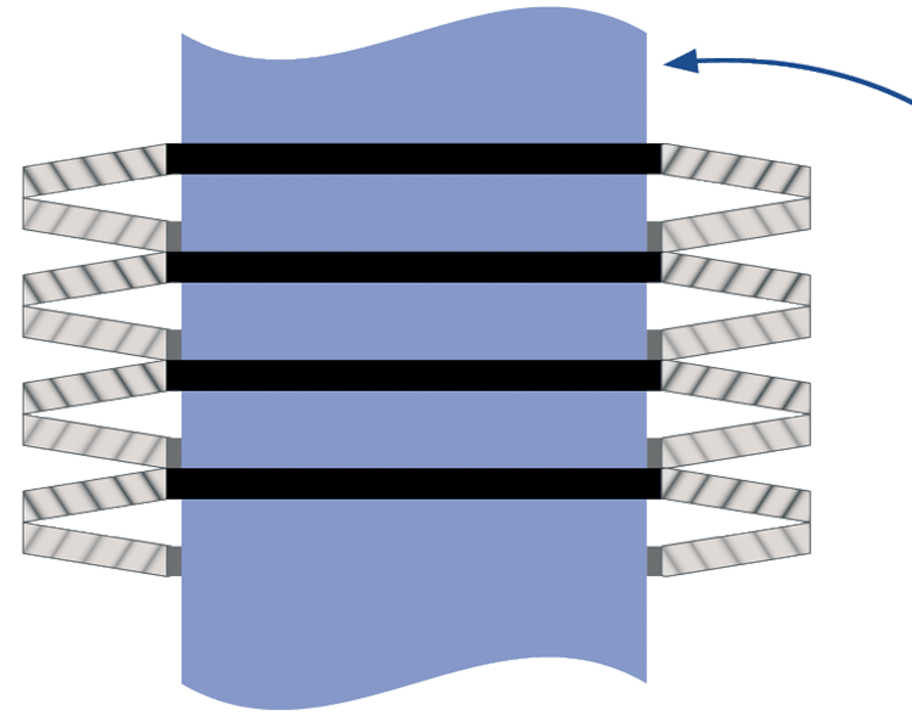
If the traditional solution is a helical coil spring but you cannot tolerate the side loading that occurs during compression, then Type 1 elements could be an alternate solution.
Using the lip and flange design to replace the coil spring, Type 1 could reduce friction and wear on mating parts, allowing your component to work as intended.
The image in blue illustrates how parallel ends become angled to each other, creating side load. In grey, parallel ends remain parallel, keeping the axis of load centered.
Tunable Hysteresis
Much attention is paid to reducing the inherent hysteresis that occurs with stacked disc springs. Our manufacturing techniques and mold designs optimize the mating surfaces on each element reducing the friction in stacked springs.
In some cases, techniques can be employed to reduce hysteresis in parallel stacked elements as well. This allows for the tuning of friction levels and the incorporation of damping effects if desired.
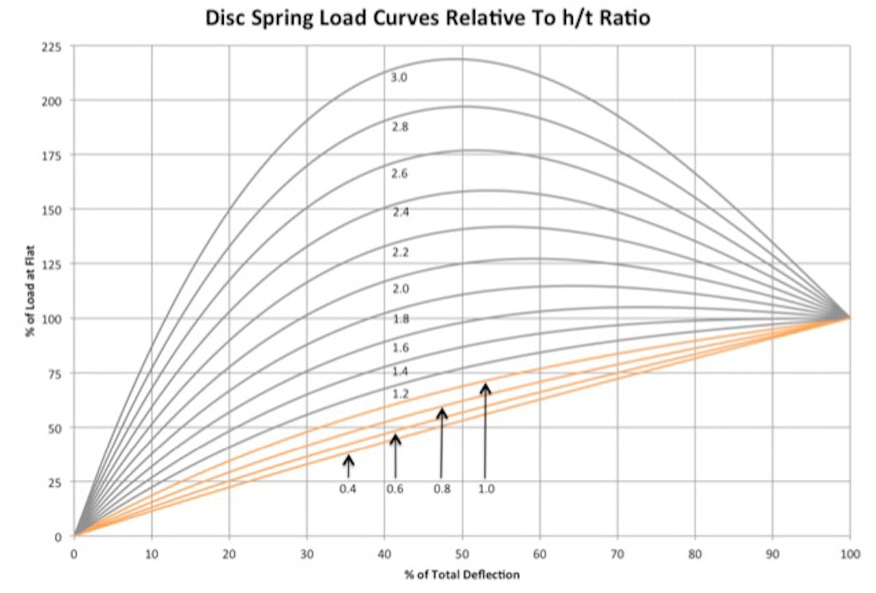
Low H/T Ratio
To the right we see the shape of a load curve of a disc spring is governed by ratio of the inside height (h) to the material thickness (t). Below is a graph showing how the h/t ratio changes the shape of the load curve. Our composite disc springs typically have an h/t of .6 – .8, through .4 – 1.0 is possible. (orange lines in the graph below)
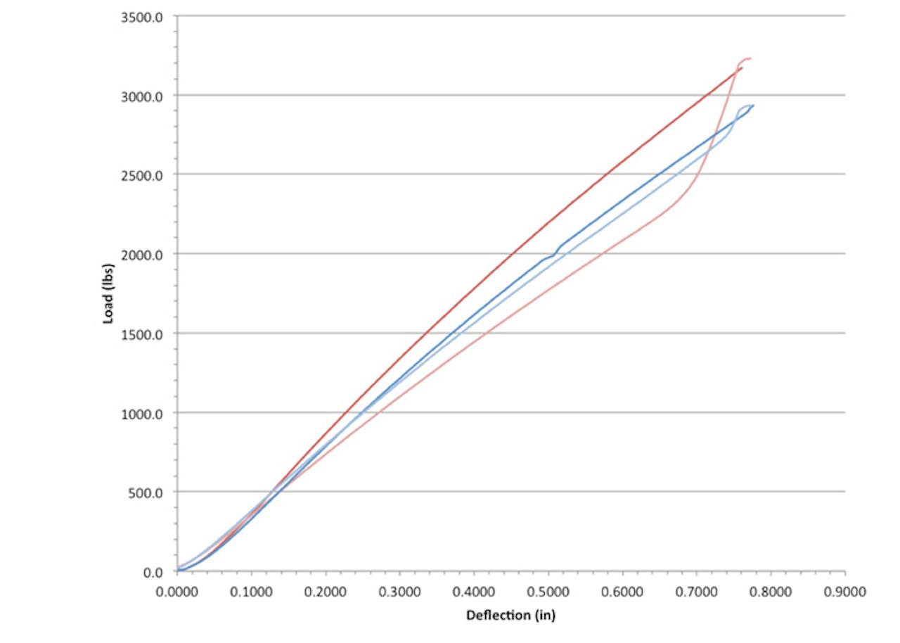
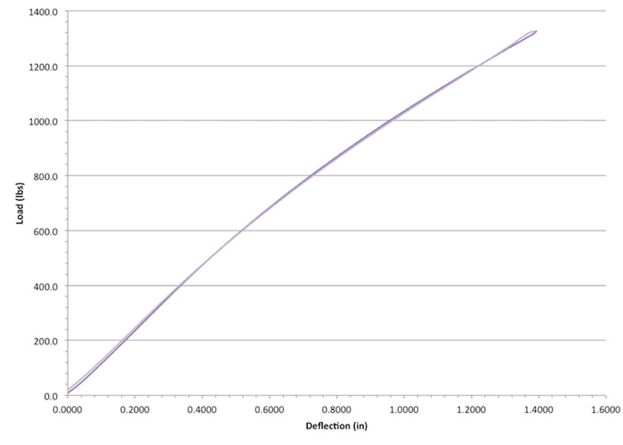
Graphs
The graphs below show parallel stack with adjustable hysteresis (left) and all series stack with ultra-low hysteresis (right).
Other Belleville Washer / Disc Spring Products
Our Manufacturing Locations
Need a Large Order?
We can design and manufacture a component for your specific application in any quantity. For quantities over 1,000, please request a quote.